High-voltage systems carry electricity from power stations to substations, industrial facilities, and distant communities. Their performance depends on a coordinated network of equipment: transformers adjust voltage, switchgear controls circuits, and protective devices isolate faults before damage spreads. Together, these components help deliver large amounts of power efficiently while managing serious electrical and operational risks.
High-Voltage System Architecture and Voltage Classes
High-voltage networks connect generation, transmission, and substations, where electricity is stepped up or down to suit each stage. Raising voltage for transmission reduces current for a given power level, which helps limit resistive losses over long distances.
Voltage labels vary across jurisdictions and technical standards. A class described as high voltage in one context may be treated as medium voltage elsewhere, so equipment ratings must follow applicable utility specifications and standards.
| System Element | Typical Role | Examples |
|---|---|---|
| Transmission | Moves bulk electricity over distance | 138 kV, 230 kV, 500 kV AC |
| Substation | Changes voltage or redirects power | Transformers, switchgear, busbars |
| HVDC link | Connects distant or asynchronous grids | Long-distance and submarine transmission |
AC remains widespread because transformers make voltage conversion straightforward. HVDC is often selected for long-distance or underwater links, where it can reduce transmission losses and connect grids that do not operate in synchronism.
Switchgear Components for Control and Isolation
Switchgear groups devices that control, isolate, and protect electrical circuits. Its design may use air, gas, or other insulation systems, with the choice shaped by voltage, available space, environmental conditions, and maintenance requirements.
Several components work together to manage current and create safe isolation. Their functions are distinct, but protection depends on coordinated operation across the assembly.
Switching Devices and Circuit Protection
Circuit Breakers interrupt fault current automatically when protective systems detect abnormal conditions. Disconnectors provide visible or otherwise verified isolation for maintenance; they are not generally intended to interrupt fault current. Busbars distribute power between incoming and outgoing circuits within a substation.
Protective Relays monitor electrical quantities and signal breakers to trip when faults occur. Correct relay settings and coordination help isolate the affected section while keeping the rest of the network in service.
Measurement and Surge Protection
Current Transformers and Voltage Transformers reduce current and voltage to measurable levels for instruments and relays. Surge Arresters limit overvoltages caused by lightning or switching events, while Insulators support energized conductors and prevent unwanted current paths.
Insulation and clearances matter as much as switching capacity: inadequate spacing or deteriorated materials can lead to flashover. Selection and installation must therefore account for operating voltage, transient overvoltages, and the environment around the equipment.
Transformers in Transmission and Substations
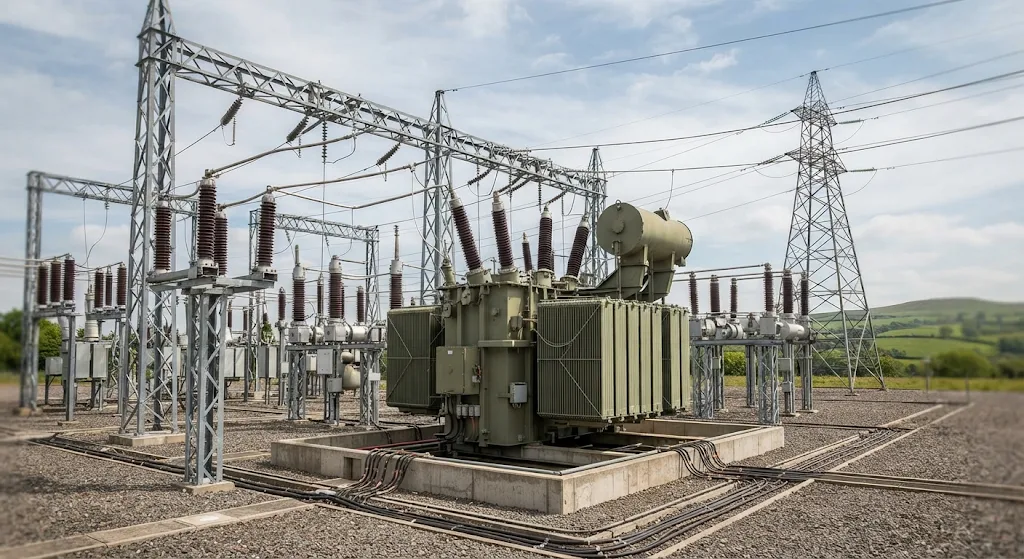
Transformers change voltage to match the needs of generation, transmission, and distribution. At a power plant, a step-up transformer raises generator output for transmission; at a substation, a step-down unit lowers it for regional networks or large facilities.
Large power transformers commonly use oil for insulation and cooling, and some include on-load tap changers to regulate output as grid conditions change. Their condition can be assessed through inspections and tests, including analysis of insulating oil and evaluation of bushings.
Transformer Placement and Grid Function
Transmission substations link generating stations to high-voltage lines, while switching substations redirect power without necessarily changing voltage. Distribution substations then reduce transmission voltage to medium-voltage levels for local networks.
The transformer’s rating must match expected demand, fault conditions, and system design. Poor coordination with breakers and relays can expose equipment to stresses it was not designed to withstand.
High-Voltage Safety, Maintenance, and Modern Monitoring
High-voltage faults can produce dangerous currents, intense heat, and pressure waves. Safe work relies on trained personnel, controlled access, appropriate protective equipment, grounding, and formal isolation procedures before maintenance begins.
Operational programs commonly combine scheduled inspection with condition-based monitoring. Useful practices include:
- Inspecting for oil leaks, damaged insulators, corrosion, and visible signs of overheating.
- Using thermal imaging and insulation tests to identify developing defects.
- Checking relay settings, breaker operation, and grounding against system requirements.
- Keeping current equipment records, test reports, and single-line diagrams.
Digital sensors can track temperature, vibration, and partial discharge, helping operators spot deterioration before it causes an outage. Still, monitoring supports rather than replaces qualified inspection: high-voltage equipment requires specialist engineering judgment and work practices tailored to the installation.